[Update May 21, 2011: click here for additional information about Make Part Compatible function for 7 Series FPGAs]
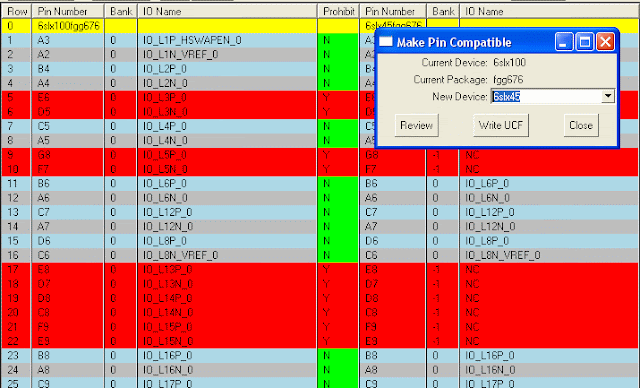
The "Tools->Make Part Compatible" function checks the pin compatibility between current selected part and a new device in the same package. The tool creates a spreadsheet that lists all pins from both parts side by side and highlights incompatible pins in red. The “PROHIBIT” column for all incompatible pins are set to yes (“Y”). Once the spreadsheet is reviewed, users can write out a UCF file with PROHIBIT constraints added for all incompatible user IOs.
Friday, September 25, 2009
Thursday, September 24, 2009
Generate Orcad Symbol
ADEPT can export a CSV file that can be directly copied and pasted to Orcad Capture part generation spreadsheet to generate a multi-part symbol for the selected device.
Orcad 10.5 or newer is required because the "New Part from Spreadsheet" function was first added to version 10.5. For users with older versions of Orcad, the "Tools->Generate Part" function in Orcad should still work(http://www.orcad.com/documents/community.faqs/capture/cap03022.aspx) with simple changes to the CSV file exported in ADEPT.
Orcad 10.5 or newer is required because the "New Part from Spreadsheet" function was first added to version 10.5. For users with older versions of Orcad, the "Tools->Generate Part" function in Orcad should still work(http://www.orcad.com/documents/community.faqs/capture/cap03022.aspx) with simple changes to the CSV file exported in ADEPT.
- Run ADEPT
- Load target device
- Run "File->Export CSV for Orcad Symbol" to export all pins (user I/Os, configuration pins, power pins, etc) to a csv file (say orcad_symbol.csv) that has the same columns as the Orcad symbol spreadsheet
- Open the csv file orcad_symbol.csv in MS Excel. Scroll down to the last row and take note of the section number (the last column). The section number is the number of parts that will be generated for the device
- Run Orcad Capture and select "New Part From Spreadsheet". On the "New Part Creation Spreadsheet" window, enter a part name in "Part Name" box, the section number above in the "No. of Sections" box, and select "Numeric" for "Part Numbering". This step MUST be done first for the section numbers to show up correctly for each pin.
- Go back to MS Excel and select rows 7 to the last row and columns A to G. Press CTRL-C to copy the selection to clipboard.
- Switch to Orcad Capture "New Part Creation Spreadsheet" window and select the first cell in the spreadsheet. Press CTRL-V to paste the clipboard content to the spreadsheet. Click "Save" to save the part. You now have a Orcad symbol with multiple parts: one part per bank (including bank 0 and MGT banks), one part for VCC*, one part for GND.
Subscribe to:
Comments (Atom)
